
Krueger flaps, or Krüger flaps, are lift enhancement devices that may be fitted to the leading edge of an aircraft wing. Unlike slats or droop flaps, the main wing upper surface and its nose is not changed. Instead, a portion of the lower wing is rotated out in front of the main wing leading edge. The Boeing 707 and Boeing 747 used Krueger flaps on the wing leading edge. Several modern aircraft use Krueger flaps between the fuselage and closest engine, but use slats outboard of the closest engine. The Boeing 727 also used a mix of inboard Krueger flaps and outboard slats, although it had no engine between them.
Operation
While the aerodynamic effect of Krueger flaps may be similar to that of slats or slots (in those cases where there is a gap or slot between the flap trailing edge and wing leading edge), they are deployed differently. Krueger flaps, hinged at their foremost position that once deployed actually become their trailing edges, hinge forwards from the under surface of the wing, increasing the wing camber and maximum coefficient of lift. [1] It produces a nose-up pitching moment. Conversely, slats extend forwards from the upper surface of the leading edge. Also, when deployed, Krueger flaps result in a much more pronounced blunt leading edge on the wing, helping to achieve better low-speed handling. This allows smaller-radius wing leading edges, better optimized for cruise. Leading edge Krueger flaps enhance wing's low speed lift production especially on swept wing aircraft. [2]
Variable Camber Krueger Flap
The Krueger flaps developed for the Boeing 747 were constructed from fiberglass material and were designed to be intentionally distorted into a much more efficient aerofoil section on deployment. [3]
Invented by James B. Cole and Richard H. Weiland of Boeing in the mid-1960s [4], the "VCK" (Variable Camber Krueger) flaps deployed from the lower leading edge of the wing similar to rigid panel Krueger flaps. The high speed lower wing in that region of the wing is a straight line normal to the wing leading edge, so the stowed panels are nominally flat, albeit twisted a small amount along the leading edge of the wing. Using two sets of identical linkages per flap, the fiberglass panel is deployed and bent to an optimal aerodynamic shape for low speed flight, while a separate aluminum folding nose that is stowed inside the wing is deployed tangent to the fiberglass panel. [5]
The Boeing 747-8 wing was redesigned with optimized VCK flap panels that were similar to the original 747.
Another airplane that used VCK flaps was the Boeing YC-14.
History
Krüger flaps were invented by Werner Krüger in 1943 and evaluated in the wind tunnels in Göttingen, Germany. [6] One of the earliest civil applications was the Boeing 707, whereas the Swiss company FFA claimed the first use of the flap in its FFA P-16 fighter which flew in 1955. [7] The flap was added to prevent wing stall with an extreme attitude take-off with the tail dragging on the runway, a scenario that had caused two de Havilland Comet accidents. A preliminary flight test had been made on the Boeing 367-80 (the Dash 80) using a fixed flap and a skid on the after-body. [8] After the Boeing test flight on the B-707 prototype on 15 July 1954, Krueger flaps were first used in production for the Boeing 727 which made its maiden flight on 9 February 1963. [9]
-
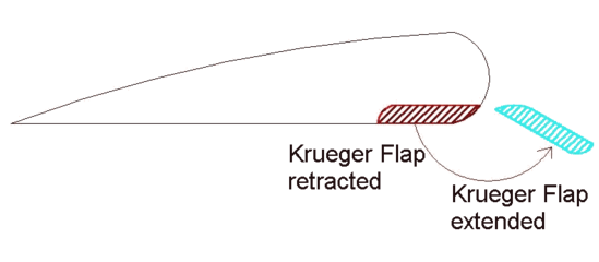 Krueger flap operation
 -
 Slat operation


Boeing conducted a series of test flights in 2015 with a modified Boeing 757, incorporating new wing-leading-edge sections and an actively blown vertical tail. [10] The left wing was modified to include a 6.7 m-span glove section supporting a variable-camber Krueger flap to be deployed during landing, protruding just ahead of the leading edge. Although Krueger flaps had been tried before as insect-mitigation screens, previous designs caused additional drag. The newer design is variable-camber and retracts as seamlessly as possible into the lower wing surface. Increasing natural laminar flow (NLF) on an aircraft wing can reduce fuel burn by as much as 15%, but even small contaminants from insect remains could trip the flow from laminar to turbulent, destroying the performance benefit. The test flights were supported by the European airline group TUI AG and conducted jointly with NASA as part of the agency’s Environmentally Responsible Aviation (ERA) program.
See also
References
- ^ Gary V. Bristow (2002). Ace the Technical Pilot Interview. McGraw-Hill Professional. ISBN 0-07-139609-8. Retrieved 2009-02-16.
- ^ Wyatt, David (21 August 2014). Aircraft Flight Instruments and Guidance Systems: Principles, Operations and ... ISBN 9781317938316. Retrieved 16 July 2020.
- ^ Taylor 1990, p. 114.
- ^ U.S. Patent 3,504,870
- ^ J. B. Cole (Dec 17, 1966), Design of the Variable Camber Flap
- ^ Niels Klußmann; Arnim Malik (2012). Lexikon Der Luftfahrt. Springer. pp. 193–. ISBN 978-3-642-22500-0.
- ^ X-Planes of Europe II, Tony Buttler Hikoki Puplication 2015. Page 193. ISBN 978-1-9021-0948-0
- ^ "The Road to the 707" Cook, William H., TYC Publishing Company, Bellevue, 1991, ISBN 0-9629605-0-0, p.249
- ^ Hitchens, Frank (25 November 2015). The Encyclopedia of Aerodynamics. ISBN 9781785383250. Retrieved 16 July 2020.
- ^ "757 EcoDemo Focuses On Laminar And Active Flow". Aviation Week. 23 March 2015. Retrieved 23 March 2015.
Sources
- Taylor, John W.R. The Lore of Flight, London: Universal Books Ltd., 1990. ISBN 0-9509620-1-5.