-
 Wikipedia logo
 -
 New Year tree
 -
 Flowers
| Draft article not currently submitted for review.
This is a draft Articles for creation (AfC) submission. It is not currently pending review. While there are no deadlines, abandoned drafts may be deleted after six months. To edit the draft click on the "Edit" tab at the top of the window. To be accepted, a draft should:
It is strongly discouraged to write about yourself, your business or employer. If you do so, you must declare it. Where to get help
How to improve a draft
You can also browse Wikipedia:Featured articles and Wikipedia:Good articles to find examples of Wikipedia's best writing on topics similar to your proposed article. Improving your odds of a speedy review To improve your odds of a faster review, tag your draft with relevant WikiProject tags using the button below. This will let reviewers know a new draft has been submitted in their area of interest. For instance, if you wrote about a female astronomer, you would want to add the Biography, Astronomy, and Women scientists tags. Editor resources
Last edited by
Bearcat (
talk |
contribs) 2 months ago. (
Update) |
It has been suggested that this page should be
split into pages titled
ZX Spectrum basic graphics mode and
ZX Spectrum non-basic graphics modes. (
discuss) (February 2024) |
This article has multiple issues. Please help
improve it or discuss these issues on the
talk page. (
Learn how and when to remove these template messages)
|

The original ZX Spectrum computer produces a one bit per pixel, bitmapped color graphics video output. A composite video signal is generated through an RF modulator, and was designed for use with contemporary 1980s television sets.
The image size of the framebuffer is 256x192 pixels, with a palette of 15 non-modifiable colors, where the entire color palette is extremely saturated. The resolution of the color output is 64 times lower than the resolution of the pixel bitmap. [1] [2] The extremely low color resolution was used to conserve memory, totaling just 768 bytes for color attributes. Color is stored separate from the pixel bitmap, as a 32x24 cell grid, using one byte per each of the character cells. One character cell is composed of 8x8 pixels. In practice, this means any character cell can only use two selected colors for coloring the contained 64 pixels. [3]
Since the machine was designed for usage with a standard television set, the 256x192 pixel area is surrounded by a wide border that fills up the remaining space of the standard 384x288 low-resolution PAL TV visible screen area. Usually, the border area assumes a single color, but using software tricks it is possible to display some low resolution graphics there. [4]
The ZX Spectrum lacked dedicated hardware for scrolling and sprites, or a dedicated hardware blitter. To facilitate the display of color graphics, the original ZX Spectrum employs 16 KiB of discrete graphics RAM. The latency of the graphics RAM is 150 ns; the peak bandwidth is 2.1875 MB/s (calculated as 224x5/8 bytes per 64 μs). [5]
Frame Rate and Timings
The original ZX Spectrum doesn't conform strictly to the PAL standard frame rate of 50 Hz. ZX Spectrum outputs one video line in exactly 224 CPU clock cycles, where the CPU clock rate equals 3.5 MHz. This exactly matches the PAL standard 64 μs line time. However, the ZX Spectrum produces only 312 lines to form one display frame, while the PAL standard recommends 312.5 lines. As a consequence, the frame rate of the ZX Spectrum is approximately 50.08 frames per second. [6]
This discrepancy was not known to many programmers, who assumed the frame rate of 50 frames per second.[ citation needed] As a result, some programs, including the built-in BASIC interpreter, had the time running little too fast. Later ZX Spectrum models have a slightly different frame rate and the CPU clock rate, which causes some older software to run slightly too slow if it uses vertical synchronization, or too fast if it relies on CPU clock rate. [6]
At the start of each display frame, the maskable interrupt signal is sent to the ZX Spectrum's Z80 CPU, enabling programs to easily detect and measure the passage of time. It also allows the programs to perfectly synchronize the graphics output with the display of video frames. It is exactly the same mechanism as the vertical synchronization of a modern computer, which can be employed to prevent display tearing.
| ZX Spectrum 16K, 48K, and ZX Spectrum+ [7] | 128K, +2, +2A, +3 [8] | |
|---|---|---|
| CPU cycles per PAL line | 224 | 228 |
| PAL line time | 64 μs | 64.28 μs |
| PAL lines per frame | 312 | 311 |
| Frame time | 19.968 ms | 19.9915 ms |
| Frame rate | 50.08 frames per second | 50.02 frames per second |
| Display Vertical Synchronization | available, by the Z80 maskable interrupt line (INT) [9] | available, by the Z80 maskable interrupt line (INT) [9] |
Graphics memory structure and pixel coordinates
The 16 KiB discrete graphics RAM is directly accessible to the CPU at addresses 16384 to 32767. The main pixel bitmap is stored at the very beginning of the graphics RAM, while the attributes array follows immediately behind it. [10]
The video controller circuit is built into the semi-custom Ferranti ULA integrated circuit, consisting of approximately 480 configurable cells (depending on the model). The cells of the ULA were factory-configured in various ways to produce the ULA for ZX Spectrum, where one cell has the functionality of approximately two NAND gates. [11]
An CPU access to the graphics RAM is called a contended access, because the video controller has a higher priority then the CPU. On an access to the graphics RAM, the CPU commonly incurs a slight delay while waiting for the video controller to complete the data reads. [12]
The addresses in the video DRAM are interleaved, which produces an unusual coordinate system for the pixel bitmap. If coordinates of a pixel are (x, y), and the bits of the x coordinate axis are labeled x7, x6, x5, x4, x3, x2, x1, x0, and the bits of the y coordinate axis are labeled y7, y6, y5, y4, y3, y2, y1, y0, then the pixel is stored in a byte with the address bitpattern 0, 1, 0, y7, y6, y2, y1, y0, y5, y4, y3, x7, x6, x5, x4, x3. [13]
The address bitpattern contains two more bitpattern transpositions than necessary. The fastest and the simplest bitpattern would have been 0, 1, 0, x7, x6, x5, x4, x3, y7, y6, y5, y4, y3, y2, y1, y0, which makes the pixel addresses increase by the column first. Unfortunately, the ZX Spectrum designers were working under extreme time pressure, and failed to notice this simple improvement. [11]
While the original ZX Spectrum 48K model has 32 KiB of main RAM, the 16K model has just the 16 KiB graphics RAM. This is the reason why the color attributes array was designed to fit in just 768 bytes. The color attributes could have easily had a double or a quadruple resolution in the vertical axis, but that would have reduced the remaining free memory space for programs by another kilobyte or two, especially in the 16 KiB model.
To facilitate the display of color graphics, the original ZX Spectrum employs 16 KiB of discrete graphics RAM, unlike the shared graphics RAM architectures of most other microcomputers, including the Commodore 64.[ citation needed] The resolution of the pixel bitmap is similar to that in other contemporary microcomputers, where the popular Commodore 64 commonly uses the 160x200 resolution at two bits per pixel. [14]
The system of color cells, called "the attributes", drew a lot of criticism, because it significantly complicated the programming of color applications.[ citation needed] Still, the color attribute system had sufficient capabilities for supporting the common applications and games of the era, and even the very limited color capabilities were welcomed by the users.[ citation needed]
Color palette

The ZX Spectrum (and compatibles) computers uses a variation of the 4-bit RGBI palette philosophy (also used on CGA, Thomson MO5, Sharp MZ-800, Mattel Aquarius, etc.), resulting in 8 basic colors with brightness variations. [15] On the 128, +2 and +3 models, the ULA outputs TTL level red, green, blue and sync signals that are used by the TEA2000 Video Encoder for composite video signal generation. [16] [17] [18] [19]
Each of the colors of the 3-bit palette has a basic and a bright variant. [15] The bright half of the palette is generated using the video displays' maximum voltage level for the luminance signal. The basic half of the palette is generated by simply reducing the voltage of the luminance signal. [20]
Both colors of a character cell cell must share their brightness property, because there is only a single brightness bit for the entire cell. Besides that limitation, any combination of the palette colors can be freely selected as the two colors of a character cell. In the following table, all the "bright" colors are given in the right column.
Color
numberBinary value Color
nameBinary value Color
nameG R B I G R B I 0 0 0 0 0 #000000 Black 0 0 0 1 #000000 "Bright" Black 1 0 0 1 0 #0100CE Blue 0 0 1 1 #0200FD Bright Blue 2 0 1 0 0 #CF0100 Red 0 1 0 1 #FF0201 Bright Red 3 0 1 1 0 #CF01CE Magenta 0 1 1 1 #FF02FD Bright Magenta 4 1 0 0 0 #00CF15 Green 1 0 0 1 #00FF1C Bright Green 5 1 0 1 0 #01CFCF Cyan 1 0 1 1 #02FFFF Bright Cyan 6 1 1 0 0 #CFCF15 Yellow 1 1 0 1 #FFFF1D Bright Yellow 7 1 1 1 0 #CFCFCF White 1 1 1 1 #FFFFFF Bright White
- Some ZX Spectrum clones or NTSC machines might display "bright black" as dark grey.[ citation needed]
- The luminance of colors in the table is relative, not absolute. The common television sets usually had much higher luminance than the standard sRGB LCD luminance of 80 cd/m². In absolute terms, ZX Spectrum's colors are much brighter then the sRGB colors in the table. ZX Spectrum's "White" color is as bright as the brightest sRGB white color, while the "Bright White" exceeds the limits of the standard sRGB color luminance.
- The given sRGB values for green, yellow and cyan are only best approximations, because sRGB displays are unable to produce all the colors of the PAL TV standard. The green PAL phosphor is out-of-gamut in the sRGB color-space of the modern common LCD displays. For most purposes, this color inaccuracy is small.[ citation needed]
- Colors simulated as sRGB assume non-bright as 84.615% voltage (0.55 V) and bright as 100% (0.65 V). [20] Each ZX Spectrum model used different voltages for colors, so the values here are only indicative. The colors were computed by a conversion of the PAL TV color-space into the sRGB color-space. The PAL gamma of 2.8 was applied as recommended by the BT.470 PAL standard; the conversion of primary colors to sRGB primaries (by IEC 61966-2-1 sRGB standard), and the standard sRGB gamma correction (by inverse EOTF) was applied.
- The given colors are probably not the real ZX Spectrum colors. The color approximations were computed by assuming the maximum possible saturation that a ZX Spectrum can produce on the PAL TV output. The real ZX Spectrum colors are currently unknown[ clarification needed], and they are probably less saturated. To compute the real ZX Spectrum colors, a measurement of the phase-amplitude shift of the chroma sub-carrier has to be performed, for each color, by an oscilloscope on the ZX Spectrum's PAL output.[ citation needed]
In the ZX Spectrum encoding, the color components are in the GRB (Green, Red, Blue) order, rather than the more common RGB order. The GRB order has the advantage that the color numbers become ordered by increasing luminance, so if viewed on black-and-white display the ordered sequence forms a gradient from black to white.
All the color properties of a cell are stored in memory as one byte called the attribute. Counting from least to most significant bit, an attribute byte dedicates three bits for color of the pixels valued 1, three bits for color of the pixels valued 0, one bit for the brightness flag, and one bit for the flashing effect. The flashing effect causes the displayed foreground and background colors to alternate every 0.64 seconds. [21]
Most current ZX Spectrum emulators are displaying inaccurate and possibly over-saturated colors.[ citation needed] Those colors were computed by simplistic approximations that don't take into account many subtleties of the PAL-to-sRGB color-space conversion. Similarly, on the ZX Art website the usage of inaccurate colors is very common.[ citation needed] The theoretically impossible sRGB color #00CD00 is commonly used as the ZX Spectrum's green color (i.e. the Spectrum's real green color is probably more bluish).[ citation needed]
BASIC commands for colors
The two colors of a character cell are called the foreground color and the background color. For any value of n from 0 to 7, the following Sinclair BASIC commands can be used to set or alter the colors of a cell: [15]
PAPER n, the background color for the character cell; applied to all pixels of value 0 in the cellINK n, the foreground color for the character cell; applied to all pixels of value 1 in the cellBRIGHT i, selects the value of the brightness bit of the character cell, where the value can be either 0 or 1
Additionally, the BORDER command selects a color for the screen area surrounding the pixel bitmap. It does not use a brightness flag, thus only the eight basic colors are supported for the border color.
[22]
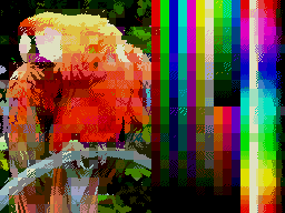
Standard mode

The original ZX Spectrum has a screen resolution of 256x192 pixels. [23] [24] In all cases, colors are extremely saturated. Color information is overlaid onto this as a grid of 8x8 pixel regions known as attribute blocks. [25] [26] All color properties of an attribute block are stored in memory as a single attribute byte, and each attribute block matches one character cell. Within each attribute block, only two colors may be used out of a palette of 8 colors. Additionally, the entire attribute block may be designated as 'bright', resulting in a total of 15 possible colors (black has no 'bright' variation). In many programs, this limitation of only two colors per attribute block is evident as the unwanted effect of attribute clash.
A screen in this mode occupies 6144 bytes for the pixel bitmap, totaling 6912 bytes together with the color attributes.
- Details:
- Pixels: 256 x 192
- Attributes: 32 x 24
- Colors: 15 (counting non-bright and bright)
- Machine: All
Standard mode gallery


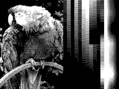
Monochrome TVs and monitors

By using a monochrome monitor or black and white TV (or reducing the saturation settings of a color TV), it is possible to take advantage of the differences in intensity over the Spectrum's color range to generate a 15-shade greyscale image at 256x192 resolution.
- Details:
- Pixels: 256 x 192
- Attributes: 32 x 24
- Colors: 15 greyscale
- Machine: All, using a monochrome display
Hi-Color attributes
Hardware implementation
Hi-Color / Multitech

Several third-party Spectrum clones, including the
Timex Sinclair machines,
[27]
[28] the
Pentagon, the
eLeMeNt ZX, and the
MB03+ Ultimate interface support a screen mode named Hi-Color,
[28] in which attribute blocks are 8x1 pixels in size rather than the usual 8x8.
[29]
[30] A screen in this mode takes 12 KB RAM. In the case of the Timex, this mode is activated through the command OUT 255,2.
[27]
[28] At least one editor for Timex machines supports this mode.
[31] In addition, this screen mode can be generated through the use of the MB-02 disk system's
DMA hardware
[32] (where the technique is known as Multitech
[33]), and is also available as Mode 2 (with a linear byte order) on the
SAM Coupé.
[34]
- Details:
- Pixels: 256 x 192
- Attributes: 32 x 192
- Colors: 15
- Machine: Timex Sinclair models, ZX Spectrum Next, Pentagon, eLeMeNt ZX, SAM Coupé
- Interface: MB03+ Ultimate
Software implementation
8x1 attributes / Hicolour / Multicolour / FLI / BIFROST*2 / Rainbow Generator / Rainbow Processor
On other Spectrum models, this effect can be replicated by exploiting the fact that the ULA re-reads the attribute information on every pixel row when generating the video output; it is possible to write a new value to the relevant memory location in between successive lines, and thus cause a different pair of colors to be shown. However, the Spectrum's processor is not fast enough to write to an entire row of attribute bytes in one scanline, so 8x1 attributes can only be achieved over 20 columns. [35] This technique is variously known as Hicolour, Multicolour, FLI, BIFROST*2 "SuperColour", [36] "Rainbow Generator" or Rainbow Processor [37] mode. [30]
- Details:
- Pixels: 256 x 192
- Attributes: 32 x 192 (limited to a 18x192 area)
- Colors: 15
- Machine: All (with specific code tailored for each machine's timings)
8x2 attributes / Bicolour / Nirvana+

A variation on this method is to change the row of attributes over the course of two scanlines, resulting in 8x2 pixel attribute blocks over a wider region of the screen. This mode is known as Bicolour, and can be applied to the full width of the screen through the use of the Nirvana+ engine. [38] [39]
- Details:
- Pixels: 256 x 192
- Attributes: 32 x 96
- Colors: 15
- Machine: All (with specific code tailored for each machine's timings)
4x1 / 4x2 / 4x4 attributes
A special case involves alternating between the two available colors per attribute cell for 4 pixels each, allowing each 4x1 region to be treated as an independently colourable 'pixel' (although the limitation of one brightness level per 8x1 cell is still in effect). Again, a 4x2 variant of this mode can be applied to a wider region of the screen. And a 4x4 variant can be achieved on 128K machines by timed switches between the two video RAMs (rather than re-writing the attribute data), to display the upper half of the character cells from one screen and the lower half from the other.
- Details:
- Pixels: 64 x 192; 64 x 96; 64 x 48
- Attributes: 8x1 brightness limitation
- Colors: 15
- Machine: All (with specific code tailored for each machine's timings)
-
 4x1 attributes example image
 -
 4x2 attributes example image
 -
 4x4 attributes example image


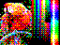
ULAplus / HAM256 / HAM8x1
ULAplus is compatible with the standard ZX Spectrum and Timex Hi-Res and Hi-Color modes, and adds the ability to redefining of the palette. [40] If only used to slight modify the basic 16 colors, ULAplus software can be displayed on a standard Spectrum. Use of the full 64 colors is incompatible, as it will trigger the "flash" attributes of the original Spectrum. [41] Amiga HAM inspired modes are also possible (HAM256 and HAM8x1), displaying up to 256 colors on screen. [42] [43] [44] [45]
- Details:
- Pixels: 256 x 192; 512 x 192 (Hi-Res mode)
- Attributes: 32 x 24; 32 x 192 (8x1 Hi-Color mode)
- Colors: 2 from 256 (Hi-Res mode), 64 from 256; 256 (HAM256 and HAM8x1)
- Machine: ZX Spectrum SE, ZX Spectrum Next, ZX-Uno, Chloe 280SE, [46] Chloe 140SE, [46] eLeMeNt ZX, zx128u+ [46]
- Interface: MB03+ Ultimate
-
 ULAplus example image
 -
 ULAplus 8x1 Hi-Color example image
 -
 ULAplus HAM256 example image
 -
 ULAplus HAM8x1 example image


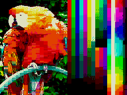
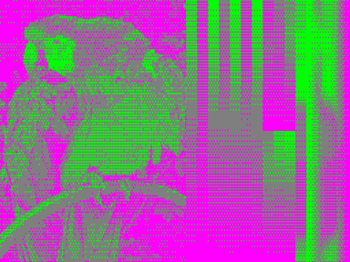
Interlace/Switched modes

Interlace
By alternating between two screens on every frame interrupt (50 Hz), it is theoretically possible to simulate a doubling of the vertical display resolution from 192 to 384 lines.
The Timex clones and ZX Spectrum 128K implement a 'shadow' screen area which can be switched into place through the use of a single OUT command, and this is often utilised to rapidly switch between two images for this purpose (although this can also be achieved with a standard block copy, albeit not over the entire screen).
When viewed on a CRT television screen (the standard at the time), the flicker is less noticeable than on a modern monitor. And example image is linked here (warning: the linked image flickers very rapidly, which could potentially cause seizures in people with photosensitive epilepsy).

The technique does not in fact achieve a true interlaced display, as the Spectrum lacks the ability to synchronise with the display hardware at such a low level. On a CRT television screen, the effect is more akin to anti-aliasing, with certain pixels appearing at half intensity. [30] [47]
On modern LCD TVs, capture cards, or other devices that convert the original analog signal into digital (thus partially ignoring the original timing signals), this mode can be interpreted as true interlace, as shown on the image featuring a cat, at the right.
- Details:
- Pixels: 256 x 384
- Attributes: 32 x 24
- Colors: 15
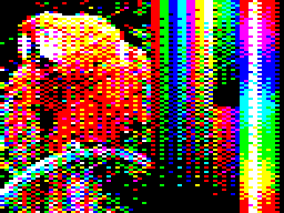
GigaScreen / DithVIDE / BZither

The attributes (colors) of an image are alternated at 50 Hz on the screen. [48] This way, the palette is increased to approximately 36 colors. [49] It's possible to switch screen per scanline and thus mix the screens, but this is very CPU intensive and needs exact and steady timings.
With real tstate precise software its possible to simulate a GigaScreen on an 128k "toastrack" original 128k ZX Spectrum. [50]
For Pentagon machines, a hardware modification is available which directly combines the two alternate screen areas into the video signal, thus eliminating the flicker associated with this method. The MB03+ Ultimate interface and the eLeMeNt ZX computer can display three hardware modes of non-flickering GigaScreen (mixed video RAMs, mixed video frames and autodetection mode) in 256 x 192 and 512 x 192 resolutions.
Furthermore, the GigaScreen and Hi-Color techniques may be employed together to produce even richer-coloured images; this format has been named DithVIDE and BZither, both names referring to the dithering methods employed when converting true-color images to the format.
- Details:
- Pixels: 256 x 192
- Attributes: 32 x 24
- Colors: ~36
- Machine: All (with flickering)
- Hardware GigaScreen: Pentagon, eLeMeNt ZX, MB03+ Ultimate (no flickering)
KeyLayer
The MB03+ Ultimate interface and the eLeMeNt ZX computer provide this graphic mode which allows to display image data from the second video RAM at the place of one selected color in the video RAM no.1. This adds a third color to an attribute.
- Details:
- Pixels: 256 x 192, 512 x 192
- Attributes: 32 x 24, 64 x 48, 3 colors per cell
- Colors: 15
- Machine: eLeMeNt ZX
- Interface: MB03+ Ultimate
3colour / Multichrome / RGB-3 / Interchrome

Three separate images, comprising a red, green and blue layer, are displayed on the screen rapidly, one after the other, relying on persistence of vision effects to merge the three layers into a single coloured image. [51] The result is an 8-color image where each pixel may be coloured independently. [52] [53]
- Details:
- Pixels: 256 x 192
- Attributes: 256 x 192
- Colors: 8
- Machine: All
Compatible machines and interfaces
Later ZX Spectrum compatible machines offered extra video modes. These are based on the standard 256x192 mode but incompatible with the original Spectrum. [30] Also interfaces, the Spectra interface and the MB03+ Ultimate interface extend the Spectrum’s display to support more colors or/and extra video modes.
16c

Video mode where each pixel can have one of 16 colors. [54]

256x192x16 / Mode 4
A Sam Coupé mode, where each pixel can display one of 16 colors from a 128 color palette. [30]
- Details:
- Pixels: 256 x 192
- Attributes: none, no limitations
- Colors: 16 (from 128) per line
- Machine: Sam Coupé
384x304x16
A mode supported by the Pentagon computer. [55]
- Details:
- Pixels: 384 x 304
- Attributes: 48 x 38
- Colors: 16
- Machine: Pentagon
HGFX Graphics
The eLeMeNt ZX computer and the MB03+ interface provide a planar-based 256x192 (LowRes), 512x192 (HighRes) and 512x384 (SuperHiRes) resolutions. [56] HGFX graphics are handled through planar layers, but can be also accessed as "chunky" RAM pages. The highest, chunky-only, is the "PAL" resolution of 720x546 pixels. The HGFX consists of ZX-screen compatible (non-linear or linear) layers-bitplanes to achieve up to 256 colors both in LowRes [57] and HiRes modes, 16 colors in SuperHiRes and 4 colors in the highest resolution. It occupies only part of the memory, similar to the ZX-screen memory, has own internal buffers and can be combined with the original ZX-graphics, in a so-called transparency mode. [58] The HGFX provides a 24-bit true-color palette (HiRes indeXedColour compatible) with a 256 indexed colors. HGFX screen data can be also displayed in HAM (Amiga-like) and FILL (Apple2GS -like) modes,
The HGFX is based on a more powerful HGFX/Q system, which was originally expandable in a border area to 320 x 240 or 640 x 240. [59]
- Details:
- Pixels: 256 x 192, 512 x 192, 512 x 384, 720 x 546
- Attributes: none, no limitations, plus FILL and HAM modes
- Colors: up to 256 (from 16777216), up to 16 (SuperHiRes) and 4 (PAL 720 x 546)
- Machine: MB03+ Ultimate, eLeMeNt ZX
Layer 2
- Details:
- Pixels: 256 x 192 (256 colors from 512), 320 x 256 (256 colors from 512) and 640 x 256 (16 colors from 512)
- Attributes: none, no limitations
- Machine: ZX Spectrum Next [60]
Radastan
This mode displays 128x96 double sized pixels. Each pixel holds one of sixteen colors, with no attribute limitations. Pixels are stored in linear buffer as 4-bit nibbles (i.e. 2 pixels per byte). The buffer is 6144 bytes long and occupies same memory as 256 x 192 pixel screen.
- Details:
- Pixels: 128 x 96
- Attributes: none, no limitations
- Colors: 16 (from 256)
- Machine: ZX-Uno, ZX Spectrum Next, MB03+ Ultimate, eLeMeNt ZX
LoRES
This mode displays 128x96 double sized pixels. Each pixel holds one of 256 colors (from 512), with no attribute limitations. Pixels are stored in linear buffer as 8-bit. The buffer is 12288 bytes long and occupies same memory as 256x192 pixel primary (DFILE1) and shadow (DFILE2) screens.
- Details:
- Pixels: 128 x 96
- Attributes: none, no limitations
- Colors: 256 (from 512)
- Machine: ZX Spectrum Next
Spectra (+128)
The Spectra has 31 display formats. These allow up to 64 unique colors to be shown simultaneously, and at a variety of color resolutions, with attribute heights of 1, 2, 4 and 8 pixels, and widths of 4 and 8 pixels. [61]
Hi-Resolution modes
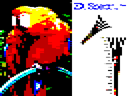
512x192x2 / Hi-Res
This mode was mainly used to display 64x24 or 85x24 columns text screen and originally only Timex Sinclair computers (where its named Hi-Res) and some Russian clones
[62] can display it. It also takes 12 KB RAM. In the case of the Timex, this mode is activated through the command OUT 255,1.
[27]
[28] Two graphics editors ("Draw 512"
[63] and "Tech-Draw"
[64]) support this mode,
[65]
[66] along with
BASIC64 and some
CP/M implementations.
[30]
- Details:
- Pixels: 512 x 192
- Attributes: none, no limitations
- Colors: 2 (Four palettes: Black & White, Blue & Yellow, Red & Cyan, Magenta & Green) (out of 512 on the ZX Spectrum Next)
- Machine: Timex Sinclair, ZX Spectrum Next, ZX-Uno, MB03+ Ultimate, eLeMeNt ZX, Pentagon
-
 512x192x2 example image with Black & White palette
 -
 512x192x2 example image with Blue & Yellow palette
 -
 512x192x2 example image with Red & Cyan palette
 -
 512x192x2 example image with Magenta & Green palette


512x192x4 / Mode 3
The Sam Coupé has this mode, where each pixel can use one of 4 colors from palette of 128. [30]
- Details:
- Pixels: 512 x 192
- Attributes: none, no limitations
- Colors: 4 (from 128) per line
- Machine: Sam Coupé

512x384x2
A mode supported by the Pentagon computer. [55]
- Details:
- Pixels: 512 x 384
- Colors: monochrome
- Machine: Pentagon, Timex Sinclair 2128 (TC 2048 based modification)
HiRes Color
Pixels are stored in a linear order. Attributes are doubled in the vertical direction, the composition of the attribute is identical to the original ZX Spectrum mode. HiRes indeXedColour can choose 32 colors from 16777216 colors. Two video RAMs can be mixed in both Color and indeXedColour modes through the Keylayer.
- Details:
- Pixels: 512 x 192
- Attributes: 64 x 48
- Colors: 16 (or 32 indexed, from 1677216)
- Machine: MB03+ Ultimate, eLeMeNt ZX
Emulated
256x192, 256 colors, "256 color mode", no attributes
The SPEC256, [67] [68] EmuZWin [69] [70] and Es.pectrum [71] emulators have a screen mode 256x192 pixels where each pixel can be in one of 256 colors. [30] This is achieved by extending the word size of the emulated Z80 from 8 bits to 64, making eight bits of data available for each pixel; the screen thus takes 48 KB of memory. This mode only exists on the emulator and software graphics must be modified to use it.[ citation needed]
- Details:
- Pixels: 256 x 192
- Attributes: none, no limitations
- Colors: 256
Dithering and Blur


The low per-pixel bit depth of only one bit per pixel has urged the graphic artists (e.g. at ZX-Art) to resort to various dithering techniques. Dithering works very well with CRT TV sets of the era, because analog televisions employ a high amount of blur in both the horizontal and vertical axis. As the focus of the common CRT TV electron beam is intentionally low, the resulting high blur produces color mixing of neighbouring pixel colors. Blur reduces the unwanted visible noise added by dithering in displayed images.
To faithfully simulate the actual output image of a ZX Spectrum, a modern emulator needs to employ a blur filter of significant strength. Simple bilinear filters introduce too much blur, while the extremely sharp Lanczos filter is inadequate. Therefore, the filter has to be specially constructed to simulate the effect of blur on a common CRT TV set. Most emulators employ filters of very low quality, causing the final image to appear extremely sharp and pixelated.[ citation needed] Some emulators, like FUSE, employ available filters in an attempt to reduce the pixilation effect.[ citation needed] Those filters produce the final image significantly different than the ZX Spectrum's real video output.
A low mutual contrast of some palette color combinations allows improvement of the dithering effect by further reducing the amount of noise introduced by dithering. The table below demonstrates this effect - for example, the contrast of a white color over a yellow background is extremely low, making the white text virtually invisible.
| 0,00,00 | 0,00,01 | 0,00,02 | 0,00,03 | 0,00,04 | 0,00,05 | 0,00,06 | 0,00,07 |
| 0,01,00 | 0,01,01 | 0,01,02 | 0,01,03 | 0,01,04 | 0,01,05 | 0,01,06 | 0,01,07 |
| 0,02,00 | 0,02,01 | 0,02,02 | 0,02,03 | 0,02,04 | 0,02,05 | 0,02,06 | 0,02,07 |
| 0,03,00 | 0,03,01 | 0,03,02 | 0,03,03 | 0,03,04 | 0,03,05 | 0,03,06 | 0,03,07 |
| 0,04,00 | 0,04,01 | 0,04,02 | 0,04,03 | 0,04,04 | 0,04,05 | 0,04,06 | 0,04,07 |
| 0,05,00 | 0,05,01 | 0,05,02 | 0,05,03 | 0,05,04 | 0,05,05 | 0,05,06 | 0,05,07 |
| 0,06,00 | 0,06,01 | 0,06,02 | 0,06,03 | 0,06,04 | 0,06,05 | 0,06,06 | 0,06,07 |
| 0,07,00 | 0,07,01 | 0,07,02 | 0,07,03 | 0,07,04 | 0,07,05 | 0,07,06 | 0,07,07 |
References
- ^ Vickers, Steven (1982). "Introduction". Sinclair ZX Spectrum BASIC Programming. Sinclair Research Ltd. Archived from the original on 24 September 2006. Retrieved 23 August 2006.
- ^ Vickers, Steven (1982). "Colors". Sinclair ZX Spectrum BASIC Programming. Sinclair Research Ltd. Archived from the original on 24 September 2006. Retrieved 23 August 2006.
- ^ EP patent 0107687, Richard Francis Altwasser, "Display for a computer", issued 6 July 1988, assigned to Sinclair Research Ltd
- ^ "Database - ZX-Art". zxart.ee. Retrieved 14 April 2023.
- ^ "48K ZX Spectrum Technical Information". worldofspectrum.org. Retrieved 28 December 2023.
- ^ a b "Spectrum Clone Design Blog".
- ^ "48K ZX Spectrum Technical Information".
- ^ "128K ZX Spectrum Technical Information".
- ^ a b Smith, Chris (2010). The ZX Spectrum ULA: How to Design a Microcomputer (1st ed.). United Kingdom: ZXDesign Technology and Media. pp. 224–227. ISBN 978-0-95-650710-5.
- ^ "48K ZX Spectrum Technical Information". worldofspectrum.org. Retrieved 15 November 2023.
- ^ a b Smith, Chris (2010). The ZX Spectrum ULA: How to Design a Microcomputer (1st ed.). United Kingdom: ZXDesign Technology and Media. p. 74. ISBN 978-0-95-650710-5.
- ^ "48K ZX Spectrum Technical Information". worldofspectrum.org. Retrieved 15 November 2023.
- ^ Tišnovský, Pavel. "Grafika na osmibitových počítačích firmy Sinclair II". Root.cz (in Czech). Retrieved 15 November 2023.
- ^ "For Newbies - C64 Video output explained". Lemon64 - Commodore 64. 24 September 2019. Retrieved 11 January 2024.
- ^ a b c "Colors - Sinclair ZX Spectrum Introduction Manual [Page 27] | ManualsLib". www.manualslib.com.
- ^ "S-video out for the ZX Spectrum +2A/+3, +2B, and +3B". zxnet.co.uk. Retrieved 20 December 2023.
- ^ "Removing Blue/Yellow Ghosting from the 128/+2's Video Output". Spectrum for Everyone. Retrieved 20 December 2023.
- ^ Farrow, Paul (2001). Spectrum 128 SCART Cable (PDF).
- ^ TEA2000 PAL/NTSC Color Encoder (PDF). Philips. September 1985.
- ^ a b "Spectrum Clone Design Blog". www.zxdesign.info.
- ^ "48K ZX Spectrum Technical Information". worldofspectrum.org. Retrieved 14 November 2023.
- ^ "Colors - Sinclair ZX Spectrum Introduction Manual [Page 27]". ManualsLib. Retrieved 14 November 2023.
- ^ "Spectrum Clone Design Blog". www.zxdesign.info.
- ^ "48K ZX Spectrum Technical Information". worldofspectrum.org.
- ^ Belfield, Dean. "L Break Into Program - ZX Spectrum Screen Memory Layout".
- ^ "World of Spectrum - Documentation - ZX Spectrum manual - Chapter 24". worldofspectrum.org.
- ^ a b c "Timex I/O Ports". timex.comboios.info.
- ^ a b c d "Timex Technical Information". worldofspectrum.org.
- ^ Weissenberg, Michael (19 December 1983). "InfoWorld". InfoWorld Media Group, Inc. – via Google Books.
- ^ a b c d e f g h "ZX Spectrum extra graphics modes -- 8bit Projects For Everyone". 8bit.yarek.pl. Archived from the original on 15 June 2006. Retrieved 14 September 2006.
- ^ "Extended Paint". www.timexsinclair.com. Retrieved 20 November 2022.
- ^ MB-02+ Revolutionary Step Forward (PDF). 8 Bit Company Laboratories.
- ^ "MB02+ download". www.128land.com.
-
^ Gordon, Wright, Bruce, Andy (1990).
SAM COUPE TECHNICAL MANUAL v3.0 (PDF). MILES GORDON TECHNOLOGY plc.
{{
cite book}}
: CS1 maint: multiple names: authors list ( link) - ^ "BIFROST*2 ENGINE at Spectrum Computing - Sinclair ZX Spectrum games, software and hardware". Spectrum Computing.
- ^ "SuperColour at Spectrum Computing - Sinclair ZX Spectrum games, software and hardware". Spectrum Computing.
- ^ "Spectrum Computing - ZX Spectrum games, software and hardware".
- ^ "NIRVANA+ ENGINE at Spectrum Computing - Sinclair ZX Spectrum games, software and hardware". Spectrum Computing.
- ^ "Database - ZX-Art".
- ^ "Database - ZX-Art". zxart.ee.
- ^ "ULAplus". sites.google.com.
- ^ "ULAplus". sites.google.com. Archived from the original on 25 May 2013. Retrieved 20 November 2022.
- ^ "ULAplus™ 10th Anniversary Collection by Source Solutions, Inc". itch.io. Retrieved 20 November 2022.
- ^ "HAM256 Viewer at Spectrum Computing - Sinclair ZX Spectrum games, software and hardware". Spectrum Computing. Retrieved 20 November 2022.
- ^ "HAM 8x1 at Spectrum Computing - Sinclair ZX Spectrum games, software and hardware". Spectrum Computing. Retrieved 20 November 2022.
- ^ a b c Gabor, Tarjan (2021). "ZX Spectrum in the 21st Century?".
- ^ "Interlace Demo at Spectrum Computing - Sinclair ZX Spectrum games, software and hardware". Spectrum Computing.
- ^ "Database - ZX-Art". zxart.ee.
- ^ "GFX ZONE - ZX-Spectrum graphics modes". gfxzone.planet-d.net.
- ^ ZX Spectrum 128k: "Velesoft's Dragon in Giga Screen Simulator" Demo (2021), retrieved 21 December 2023
- ^ "Database - ZX-Art". zxart.ee.
- ^ "ZX Prism: 16 Color "color-clash free" planar mode and Hardware Gigascreen". 17 July 2014.
- ^ "Триколор — SpeccyWiki". speccy.info.
- ^ "16col — SpeccyWiki".
- ^ a b "384x304 — SpeccyWiki".
- ^ "Graphics modes of ZX Spectrum and compatibles supported on the eLeMeNt/MB platform".
- ^ "LnxSpectrum HGFX Oxygene" – via vimeo.com.
- ^ "HGFX - ZX Planar - tutorial".
- ^ "lnxspectrum:hgfx [ilnx.cz]". wiki.ilnx.cz.
- ^ "Video Modes - SpecNext official Wiki".
- ^ Farrow, Paul (2018). Summary of SPECTRA Display Modes (PDF). www.fruitcake.plus.com / www.zxresourcecentre.co.uk.
- ^ "512x192 — SpeccyWiki".
- ^ "Draw 512". www.timexsinclair.com. Retrieved 20 November 2022.
- ^ "Tech-Draw". www.timexsinclair.com. Retrieved 20 November 2022.
- ^ "Draw 512 at Spectrum Computing - Sinclair ZX Spectrum games, software and hardware". Spectrum Computing. Retrieved 20 November 2022.
- ^ "Software for the TS 2068". www.timexsinclair.com. Retrieved 20 November 2022.
- ^ MVV (18 July 2022), mvvproject/Spec256-Games, retrieved 26 November 2022
- ^ "Spectrum Magic ZX games 256 color". spectrummagic.emuunlim.com. Retrieved 26 November 2022.
- ^ "EmuZWin v2.6 release 1.0".
- ^ "EmuZWin 2". f0460945.xsph.ru. Retrieved 26 November 2022.
- ^ "Es.pectrum manual". www.habisoft.com. Retrieved 26 November 2022.
External links
- ZX-Spectrum graphics modes
- ZX-Spectrum extra graphics modes Archived 15 June 2006 at the Wayback Machine
- Image to ZX Spec - An open source utility for image conversion from PC to ZX Spectrum (including 14 dither modes)
- Retro-X - A utility for image conversion from PC to old machines (includes non standard ZX Spectrum modes)
- ZX GIMP plug-in A GIMP plug-in to make any RGB image to look like a ZX Spectrum screen.
- BIFROST*2 Engine (Multicolour "8x1" attributes 20 columns)
- NIRVANA+ Engine (Multicolour "8x2" attributes full screen width)
- ZX-Spectrum Next Video Modes
- ZX-Spectrum graphic art collection